|
Technical Features:
|
| Introduced
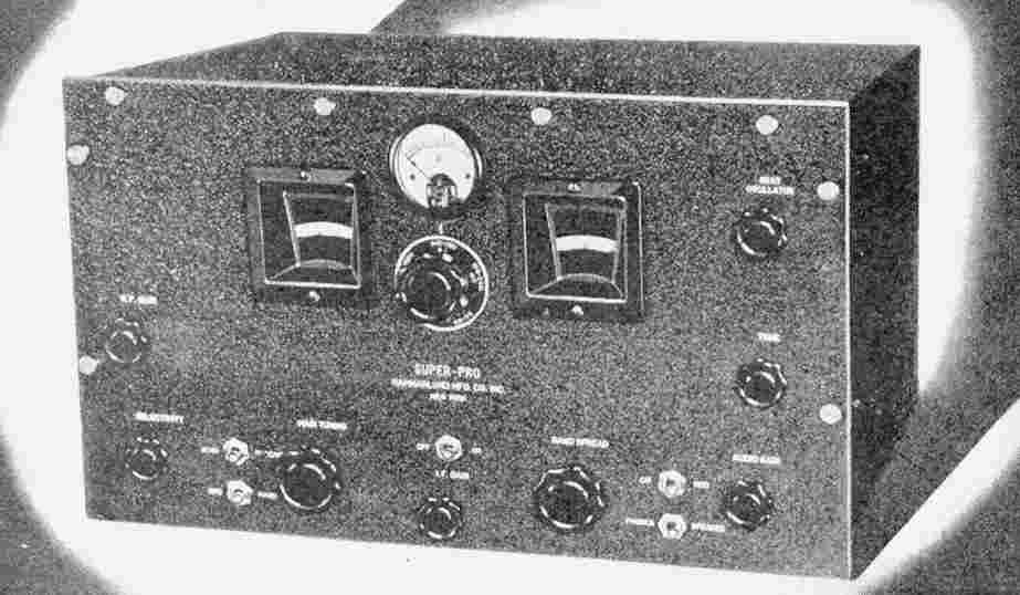
to the public in early 1936, the Super-Pro is a 16-tube
super-heterodyne receiver covering 545 KHz to 20 MHz in five
bands. The circuit includes 2 RF stages, 3 IF stages with
variable bandwidth, and a 12-watt push-pull audio amplifier.
Other features include a signal-strength meter and a calibrated
beat-frequency oscillator. There are fourteen tubes on the main
chassis and two more in the external power supply. |
 |
| The RF Front End The heart of any receiver lies in it's tuned circuits, and the Super-Pro is no exception. The main tuning dial, on the left, is directly calibrated in frequency, and offers better than 1/2% accuracy. The black slotted mask, geared to the band switch, uncovers the correct scale for the band in use. The dial on the right, is connected to the twelve-gang band-spread capacitor. The bandswitch connects the appropriate number of sections to provide an optimal spread range for the band that's in use. As a result, the major ham bands each cover the most of the 0-100 scale. Tuning is by way of a simple-but-effective friction drive that engages the edge of the dial scales. Tuning ratio is a pleasing 12:1 with no backlash. |
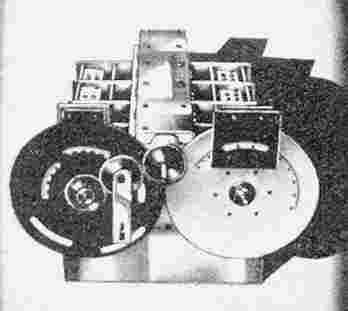 |
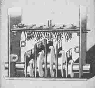
| Here's
a bottom view of the tuning assembly with the shielding removed.
Each coil assembly is mounted on a ceramic base along with it's
associated trimmer capacitor. The input coils (left) have Faraday
shields between the primaries and secondaries to maintain proper
performance with balanced antenna connections. The 12-section
band-spread capacitor is clearly visible. Careful design and through shielding provide excellent rejection of unwanted signals. Read this testamonial from an engineer at radio station WOR. |
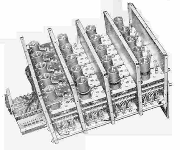 |
| Up
until this time, most designers of high-performance receivers had
eschewed band-switched designs because the performance of the available
rotary switches was not reliable. Hammarlund's solution was this
custom-designed cam-actuated band switch. The contacts are silver
plated, and the action is make-before-break to eliminate arcing in
current carrying circuits. This is just one of the five
sections. Sixty years later, most of these switchs still work
just fine with no attention whatsoever. |
 |
 |
Variable Bandwidth
Three of the IF transformers in the Super-Pro have
adjustable coupling between their primary and secondary windings.
The lower coils are moved by cam-actuated push rods. This gives a
continuously variable pass band of 3 to 12 KHz. The front-panel
bandwidth control is calibrated in kilohertz. The SP-10 and SP-100 models could be ordered with an optional crystal filter for CW reception. The crystal filter was standard on the SP-200 sets. |
 |
|
Here is a family of selectivity curves for an SP-200 receiver. ("Right Click" and "View Image" for a clearer look.) They show the selectivity for four positions of the "BAND WIDTH" control. The front-panel bandwidth scale indicates the approximate half-voltage (-6 dB) bandwidth of the IF amplifier. The fifth curve, "A", is for the 3 KC bandwidth plus the crystal filter in it's widest position (1). This chart, not only indicates the broad range of selectivity available to the operator, but also the filter's steep "skirts" that reject nearby unwanted signals. In modern practice we consider the ratio of a filters bandwidth at 6 and 60db attenuation. The Super-Pro's 3:1 "shape factor" is still very respectable today. High Fidelity Most communications receivers have a fixed IF bandwith of approximately 4-6 KHz to provide maximum intelligibility of speech, especially under difficult conditions. This limits the high-frequency audio response to 2-3 KHz. Because one of the target markets for the Super-Pro was broadcast monitoring and network rebroadcast, it was provided with this variable bandwith feature. When conditions are good, the passband can be opened up to enjoy the music. Conversely, the IF can be tightened up to a very restriced 3 KHz to "dig out" voice signals when the going gets tough.. This hi-fi capability is reinforced by a very clean sounding 14-watt audio amplifier using push-pull triode-connected tubes. It will, indeed, provide room-filling volume. A Super-Pro, connected to a good speaker system, will outperform virtually any AM broadcast receiver ever built. |