|
|
|
Buy the late 1940's it had become obvious that, in order to improve the performance of HF communications receivers, something more elaborate than a "straight" single-conversion superheterodyne was in order. Even the best of these sets, like the HRO's and Super Pro's, were lacking in the areas of frequency accuracy and stability, image rejection, and IF selectivity.
The answer, of course was the multiple conversion superhet. Build a good, stabile receiver that tunes a limited frequency range at a modest frequency, say 2-3MHz. Then use a crystal controlled converter as a front end to select the frequency band of interest. In the simple case, one needs a separate converter crystal for each 1-MHz band tuned.
The Collins 51J, introduced in 1949, pioneered this sort of architecture in commercial HF receivers. It tunes 0.5 to 30.5 MHz in 30 1-MHz bands. Through a high degree of mechanical and electrical complexity, and a few annoying compromises, it accomplishes this with only 10 crystals.
(The following historical information is derived from Racal and the RA.17 HF Communications Receiver, Keith R. Thrower, Radio Bygones, October/November 1993.)
Ray, Raymond Brown, and Cal, George Calder (Jock) Cunningham established Racal Ltd. in 1950. This led to the formation of Racal Engineering Ltd. in 1951 and a move to a 5000 square-foot building in Isleworth, near the London Airport.
 |
| Cover artwork from RA.17 manual. Could this be Ray and Cal? |
Early in 1953, Racal hoped to acquire the rights to manufacture in Britain the new Collins 51-J HF communications receiver. On the basis of this, Racal was awarded a contract with the Royal Navy for the supply of 200 of these receivers. For the manufacture of the Collins receiver, Racal proposed to use a substantial portion of British components. Unfortunately, Collins insisted that only US components be used, and after a visit to Racal's primitive facilities at Isleworth, Collins decided that Racal was too small to undertake manufacture of the radio, which was probably true at that time.
The problem facing Racal was to produce a receiver with the same general characteristics as the Collins sets to fulfill their Royal Navy contract.
Meanwhile, in South Africa, Dr. Trevor Wadley, who had worked for
the
Telecommunications Research Establishment in England during the war,
was
developing a communications receiver based on an extremely accurate and
elegant frequency control scheme that he had developed for use in test
equipment. Racal and Wadley eventually got together. The
result
was one of the world's great communications receivers. The design
work on the RA.17 was started in late 1954, and production continued at
least until 1967.
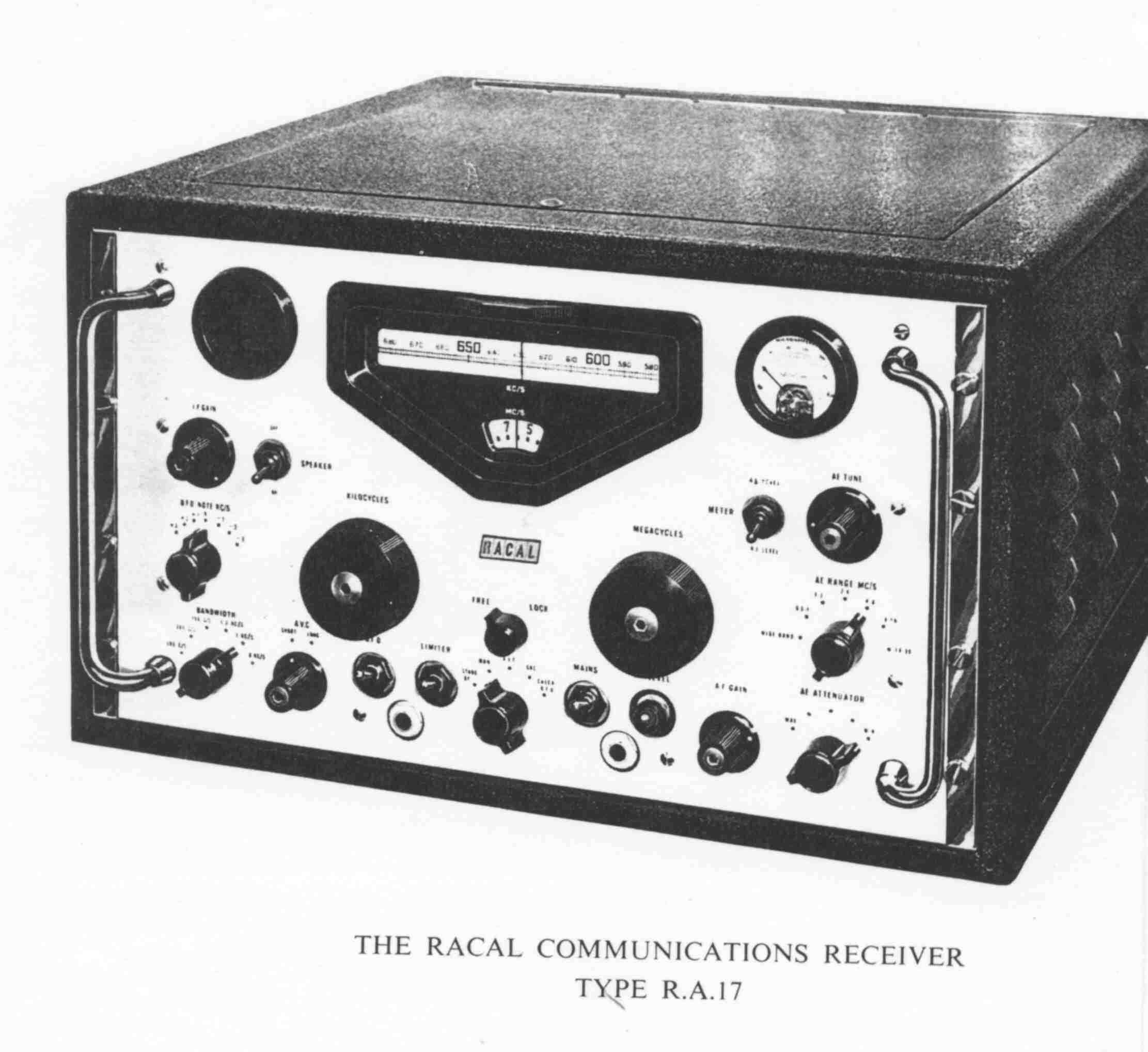
The RA.17 occupies 10 3/4 inches of rack space, which was pretty much standard communication receiver size in this era. The diecast aluminum chassis pushes the weight to 67 pounds versus 43 for the 51J. The receiver uses 22 miniature tubes plus a rectifer. The commonly available "C" models use US tubes. Tuning range is 0.5 to 30 MHz in 30 1-MHz bands. The approximately $1000 introductory price crept up to $2400 before production ended.
The front panel is dominated by the clearly Collins inspired tuning
dial bezel and two large tuning knobs. The "MEGACYCLES" knob is
the
band selector. It tunes 0 to 29 MHz in a turn and a half, has no
detents, and turns easily. You tune so the frequency you want is
in the middle of the small window and peak the noise or signal.
The
flywheel-weighted "KILOCYCLES" knob does the tuning across the selected
1-MHz band. It has a very light and precise feel; perhaps not as
smooth as a Hammarlund SP-600, but exceedingly satisfying non the less.
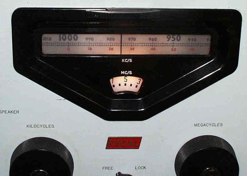
The "KILOCYCLES" dial controls the best part of the receiver, a 6-foot piece of 35mm film that serves as the kilocycle readout. It has about 20 1-KHz divisions per inch. The manual proudly points out that the 0.5 to 30-MHz tuning range is effectively spread across 145 feet! The RA.17 is my pick for the best SWL "band cruiser" of all time, offering the smooth unencumbered tuning of a high-end Hammarlund and the frequency accuracy associate with the Collins products.
The signal path through the RA.17 may be seen in the upper half of
figure
1: The antenna input is low-pass filtered (30MHz), amplified, and
upconverted to a first IF of 40MHz. Upconversion allows the
receiver
to achieve an extremely high degree of image rejection because the
image
is separate from the desired signal by twice the first IF, i.e. 80
Mhz.
After passing through a 1-Mhz-wide filter at 40 MHz, the signals are
down
converted to a tunable IF of 2-3MHz. The signals are then
converted
to a 100KHz final IF for amplification, filtering, and detection.
The local oscillator signal for the first mixer is provided by a fairly
conventional variable-frequency oscillator (VFO-1.) Because of
the
up-conversion scheme, this oscillator can tune the entire 29MHz input
range
buy providing an injection signal in the fairly limited range of 40.5
to
69.5MHz.
In a conventional design, such a free-running oscillator would be hopelessly unstable. Here's where the magic of the Wadley error-canceling "loop" comes into play. Follow along in the lower half of figure 1.
A harmonic generator and low-pass filter driven by a 1MHz crystal oscillator creates a "comb" of frequencies at 1MHz intervals from 1 to 32 MHz. Mixer M-4 translates this comb upward in frequency by an amount determined by the signal from VFO-1. If VFO-1 is tuned within 150KHz of an "even" half megahertz, one of the comb frequencies will pass through the 37.5MHz filter and amplifier and be applied to mixer M2 to converts the desired signal from the 40MHz first IF down to the 2-3MHz second IF.
The important point is that the net accuracy of the
up-conversion-down-conversion
process is established by the offset between the first and second local
oscillator signals, and this offset will always be an exact multiple of
1MHz as established by the crystal oscillator. Furthermore, this
wide range of tuning in 1MHz steps is accomplished with a single
variable
capacitor and a single oscillator coil.